| Definition: | representation on the P/Q power plane defining the active and reactive power that the EES system is designed to exchange with the electric power system via the primary POC, in steady-state operation and under continuous operating conditions
NoteĀ1 to entry: The power available is depicted by a region on the P/Q power plane. The boundaries of the region represent the operating limits of the EES system. In Figure 4, the power capability chart is divided in four quadrants by the P/Q axes (the producer reference frame as described in IEC TRĀ61850-90-7:2013 is adopted):
- in the quadrant Q1, the EES system is discharging to the electric power system and its behaviour is like that of a capacitor;
- in the quadrant Q2, the EES system is charging from the electric power system and its behaviour is like that of a capacitor;
- in the quadrant Q3, the EES system is charging from the electric power system and its behaviour is like that of an inductor;
- in the quadrant Q4, the EES system is discharging to the electric power system and its behaviour is like that of an inductor.
X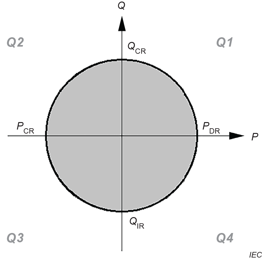
Key
| PCR | rated active power during charge |
| PDR | rated active power during discharge |
| QIR | rated inductive reactive power |
| QCR | rated capacitive reactive power |
Figure 4 – Illustrative example of a power capability chart
NoteĀ2 to entry: The watt (W) and the var are the SI coherent derived units for active power and reactive power, respectively; other units can be chosen for convenience as well (e.g. MW, Mvar). NoteĀ3 to entry: If restrictions are not declared, the power capability chart is normally valid for the entire service life of the EES system.
|